Servos
Posted on Wednesday, 21 November 2012
|
No Comments
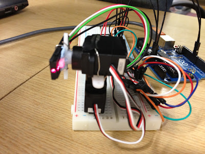
Two micro servos were sourced from previous projects, and the prototype system was set up with the laser as can be seen below.
The laser is attached to the top y axis servo, with that servo itself attached to the x axis servo underneath. These are then controlled and powered through the Arduino. The red and black wires of the servos are connected to 5V and ground respectively, with the white (yellow in the diagram below) wire connected to the digital PWM port used for control. In the prototype, pins 9 and 10 on the Arduino are used.
 |
| Wiring Diagram |
 |
| And schematic for those that prefer. |
It is worth noting that servos are fairly power hungry, so an external power supply is required if more than two are connected, this was tested. When on the robots the Arduino will be powered externally as no USB connection will be available.
The following Arduino code was developed using the Servo library and the associated example. It rotates the laser through 4 positions, with a delay of half a second between each movement.
#include <Servo.h>

Servo X;  // create servo object to control a servo
Servo Y;  // create servo object to control a servo

void setup()
{
    X.attach(9);  // attaches the servo on pin 9 to the X servo object
    Y.attach(10);  // attaches the servo on pin 10 to the Y servo object
    pinMode(13, OUTPUT);
}


void loop()
{
    digitalWrite(13, LOW); // Laser is active low so turn on

    X.write(90);     // tell servo to go to position 90 degrees
    Y.write(60);
    delay(500);

    X.write(110);
    Y.write(60);
    delay(500);

    X.write(90);
    Y.write(90);
    delay(500);

    X.write(110);
    Y.write(90);
    delay(500);
}
Hit play to see the laser moving to the positions as specified (the video has no audio).

